what is the voltage drop for a no. copper wire 50 feet long to carry 12.5 amperes
Copper Wire Resistance and Voltage Drop
AWG stands for "American Wire Judge" and is a standardized wire approximate arrangement used in the US since 1857 for diameters of round, nonferrous, electrically conducting wire. The cross-sectional area of a wire determines it's resistance and current-carrying capacity. The large the wire bore, the less resistance it has to the flow of electrons, and the more than current it can carry without overheating. The table below list copper wire resistance for various gauges of copper wire. These should be used as a rule of pollex as there are other factors that play into the current ratings of wire including ambience temperature, insulation temperature limit, air convection, etc. You should consult the National Electric Code (NEC) for specific guidelines.
AWG Wire Sizes and Resistance
| AWG approximate | Conductor Diameter Inches | Conductor Diameter mm | Ohms per 1000 ft. | ||
| 0000 | 0.46 | xi.684 | 0.049 | ||
| 000 | 0.4096 | 10.40384 | 0.0618 | ||
| 00 | 0.3648 | 9.26592 | 0.0779 | ||
| 0 | 0.3249 | 8.25246 | 0.0983 | ||
| i | 0.2893 | 7.34822 | 0.1239 | ||
| ii | 0.2576 | six.54304 | 0.1563 | ||
| three | 0.2294 | v.82676 | 0.197 | ||
| 4 | 0.2043 | 5.18922 | 0.2485 | ||
| v | 0.1819 | 4.62026 | 0.3133 | ||
| 6 | 0.162 | four.1148 | 0.3951 | ||
| vii | 0.1443 | three.66522 | 0.4982 | ||
| 8 | 0.1285 | 3.2639 | 0.6282 | ||
| 9 | 0.1144 | 2.90576 | 0.7921 | ||
| ten | 0.1019 | 2.58826 | 0.9989 | ||
| xi | 0.0907 | 2.30378 | 1.26 | ||
| 12 | 0.0808 | 2.05232 | 1.588 | ||
| 13 | 0.072 | i.8288 | 2.003 | ||
| 14 | 0.0641 | 1.62814 | 2.525 | ||
| 15 | 0.0571 | i.45034 | three.184 | ||
| 16 | 0.0508 | 1.29032 | four.016 | ||
| 17 | 0.0453 | 1.15062 | 5.064 | ||
| 18 | 0.0403 | one.02362 | 6.385 | ||
| nineteen | 0.0359 | 0.91186 | viii.051 | ||
| 20 | 0.032 | 0.8128 | 10.fifteen | ||
| 21 | 0.0285 | 0.7239 | 12.8 | ||
| 22 | 0.0254 | 0.64516 | 16.fourteen | ||
| 23 | 0.0226 | 0.57404 | 20.36 | ||
| 24 | 0.0201 | 0.51054 | 25.67 | ||
| 25 | 0.0179 | 0.45466 | 32.37 | ||
| 26 | 0.0159 | 0.40386 | 40.81 | ||
| 27 | 0.0142 | 0.36068 | 51.47 | ||
| 28 | 0.0126 | 0.32004 | 64.9 | ||
| 29 | 0.0113 | 0.28702 | 81.83 | ||
| xxx | 0.01 | 0.254 | 103.2 | ||
| 31 | 0.0089 | 0.22606 | 130.1 | ||
| 32 | 0.008 | 0.2032 | 164.one |
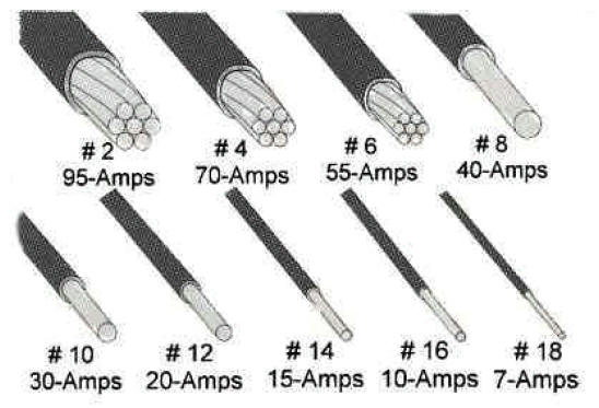
The diagram beneath shows many of the common copper wire sizes used when wiring a dwelling. General ampacity ratings are listed as well but you should consult the tables below for more accurate ampacity ratings. This illustration is meant to prove relative sizes of the common gauges of wire.
Common Copper Wire Sizes
This tabular array provides the amperage rating for common insulated conductors including Romex. Insulated conductors should have the temp rating and blazon (i.due east. THWN 75ºC) printed on the outside of the cablevision. Yous tin can then follow the chart below to see how much current y'all are immune to put through the usher. This table assumes non more than three conductors in a raceway or cable or earth (direct buried) and is based on ambient temperature of 30ºC (86ºF).
Ampacities of Insulated Conductors
| Size | Temperature Rating of Conductor | Size | |||||
| AWG | 60ºC | 75ºC | 90ºC | 60ºC | 75ºC | 90ºC | AWG |
| (140ºF) | (167ºF) | (194ºF) | (140ºF) | (167ºF) | (194ºF) | ||
| Types | Types | Types | Types | Types | Types | ||
| T TW UF | THW THWN XHHW Use | RHH THHN XHHW | T TW UF | THW THWN XHHW USE | RHH THHN XHHW | ||
| 0 | Copper | Aluminum | |||||
| 14 | 20 | 20 | 25 | ---- | ---- | ---- | ---- |
| 12 | 25 | 25 | 30 | 20 | twenty | 25 | 12 |
| x | 30 | 35 | 40 | 25 | 30 | 35 | ten |
| 8 | 40 | 50 | 55 | thirty | forty | 45 | 8 |
| 6 | 55 | 65 | 75 | 40 | fifty | 60 | half dozen |
| iv | seventy | 85 | 95 | 55 | 65 | 75 | four |
| 3 | 85 | 100 | 110 | 65 | 75 | 85 | 3 |
| 2 | 95 | 115 | 130 | 75 | 90 | 100 | two |
| one | 110 | 130 | 150 | 85 | 100 | 115 | 1 |
| 0 | 125 | 150 | 170 | 100 | 120 | 135 | 0 |
| 00 | 145 | 175 | 195 | 115 | 135 | 150 | 00 |
| 000 | 165 | 200 | 225 | 130 | 155 | 175 | 000 |
| 0000 | 195 | 230 | 260 | 150 | 180 | 205 | 0000 |
| 250 | 215 | 255 | 290 | 170 | 205 | 230 | 250 |
| 300 | 240 | 285 | 320 | 190 | 230 | 255 | 300 |
| 350 | 260 | 310 | 350 | 210 | 250 | 280 | 350 |
| 400 | 280 | 335 | 380 | 225 | 270 | 305 | 400 |
| 500 | 320 | 380 | 430 | 260 | 310 | 350 | 500 |
The table below provides the maximum number of THNN conductors that you tin can put in a given size conduit. Correction factors should be used if putting more 3 conductors in a raceway.
Maximum Number of THNN Conductors in Conduit
| Conduit Size (inches) | ||||||||||||
| AWG | 1/2 | 3/four | i | 1 1/four | i 1/2 | 2 | ii ane/2 | 3 | three 1/2 | 4 | five | half-dozen |
| 14 | 13 | 24 | 39 | 69 | 94 | 154 | ||||||
| 12 | 10 | 18 | 29 | 51 | lxx | 114 | 164 | |||||
| 10 | 6 | 11 | 18 | 32 | 44 | 73 | 104 | 160 | ||||
| eight | iii | 5 | ix | 16 | 22 | 36 | 51 | 51 | 106 | 136 | ||
| 6 | one | four | 6 | 11 | 15 | 26 | 37 | 37 | 76 | 98 | 154 | |
| 4 | i | 2 | 4 | 7 | 9 | sixteen | 22 | 22 | 47 | 60 | 94 | 137 |
| 3 | 1 | ane | 3 | 6 | 8 | 13 | xix | 29 | 39 | 51 | eighty | 116 |
| 2 | ane | 1 | 3 | 5 | 7 | eleven | 16 | 25 | 33 | 43 | 67 | 97 |
| 1 | ane | ane | 3 | v | viii | 12 | 18 | 25 | 32 | 50 | 72 | |
| 0 | 1 | i | three | four | 7 | 10 | 15 | 21 | 27 | 42 | 61 | |
| 00 | 1 | i | 2 | three | 6 | 8 | 13 | 17 | 22 | 35 | 51 | |
| 000 | i | one | 1 | 3 | 5 | 7 | 11 | 14 | 18 | 29 | 42 | |
| 0000 | 1 | one | 1 | 2 | iv | half dozen | ix | 12 | xv | 24 | 35 | |
| 250 | 1 | 1 | 1 | 3 | 4 | 7 | 10 | 12 | 20 | 28 | ||
| 300 | 1 | 1 | 1 | 3 | 4 | 6 | viii | eleven | 17 | 24 | ||
| 350 | 1 | 1 | 1 | two | 3 | five | 7 | 9 | xv | 21 | ||
| 400 | 1 | 1 | one | three | 5 | 6 | 8 | 13 | 19 | |||
| 500 | 1 | one | 1 | 2 | 4 | 5 | 7 | 11 | 16 | |||
Ampacity Correction Factors for more than 3 conductors in Raceway
| No. Conductors | 4 to half dozen | vii to 9 | 10 to 20 | 21 to xxx | 31 to forty |
| Factor | 0.8 | 0.7 | 0.5 | 0.45 | 0.four |
Why practise I need larger gauge wire to deport more current?
The larger the copper wire size the less resistance and hence the more current information technology can carry without over-heating. Resistance impedes to the flow of electrons and causes a voltage drop across the wire. You want to avoid voltage drops on your wiring equally much as possible because they generate rut and wasted energy. The calculator below will help determine how much voltage driblet you will get with a given copper wire and its associated resistance.
Voltage Drib Calculator
This calculator determines the voltage drib for an aluminum or copper wire of whatsoever gauge. You lot should by and large target less than 3% voltage driblet in a given excursion. Wire resistances are based on NEC 2008, Table eight at 75oC.
Voltage Driblet Estimator Download
The following Excel spreadsheet is a voltage drop calculator that is a piddling more avant-garde. It can be used to make up one's mind recommended wire gauges, maximum distances, or maximum amperage.
Voltage Drop Calc (.xls, 650KB)
Grounding Conductor Size Calculator
| Select rating of circuit breaker ahead of equipment, conduit, etc. Not Exceeding (Amperes) | |
| Required size of Copper grounding conductor | Required size of Aluminum grounding conductor |
| *Calculator based on 2008 NEC Tabular array 250-122. Calculator specifies minimum size grounding conductors required for grounding a raceway or equipment. Do not utilize this calculator for sizing hot conductors. | |
Source: https://www.buildmyowncabin.com/electrical/copper-wire-resistance.html
0 Response to "what is the voltage drop for a no. copper wire 50 feet long to carry 12.5 amperes"
Post a Comment